Series: All Victron RV Electrical
This series covers our build of an all Victron electrical system. Take what is helpful and leave the rest—build your system for your own needs. Cheers!
Note: We are not sponsored by Victron, but we are Amazon and Tnutz affiliates.
Part 4: Wiring and Configuration
Part 5: Orion XS 1400 – Concept
Part 6: Orion XS 1400 – Design
Part 7: Orion XS 1400 – Installation
Introduction
In the last post I went over the details of design of our DC-DC charging system. In this post I cover installation and wiring, along with setting configuration and my closing thoughts of the system.
Installation
Installation was performed in three parts:
- High Idle kit
- Truck battery to electrical cabinet
- Inside the cabinet
We were months out from receiving the Orion XS 1400 units and wanted to complete what we could while home between travels. I began work on the first two parts of the project after our winter trip in early 2025, starting with the high Idle kit.
High Idle Kit
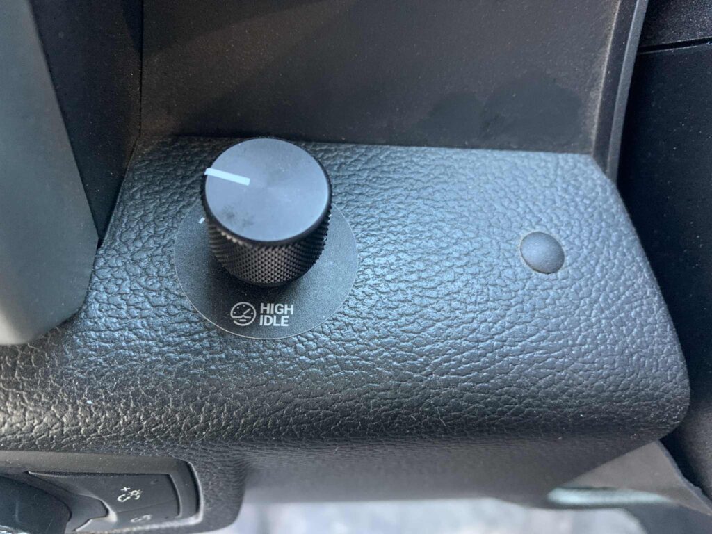
As discussed, it is a good idea to turn up engine RPM while you charge at idle. And because installation of the BD Diesel high idle kit is separate from the rest of the project, it was a good place to start.
I found several installation videos on YouTube, but this one was the best. You simply plug the cable into Ford’s wire harness, located behind the kick panel on the passenger side floor board. Next, run the cable behind the console to the driver side and connect it to the control module.
You need to decide where to attach the control module. You can use the provided bracket or mount it directly on the dash. I chose the ladder and installed it along the top of the knee bolster (bottom of dash). All that is required is drilling a 9/32″ hole. I did this using a step bit.
The entire bottom assembly of the dash below the steering wheel pops free and rotates down so you can run the cable and see what obstacles lie behind your mounting location. This is where I screwed up.
It appeared there would be sufficient clearance for both module and cable, but there was not. The module cracked when I attached the cable and snapped the dash back in place. Fart. I would love to blame the 15° weather, but this was all me.
Luckily BD Diesel tech support was super helpful. They acted like it was no big deal and sent me a replacement module for free. Canadians are awesome!
Truck Battery to Electrical Cabinet
I needed to figure out where under the hood to attach the breaker and solenoid, plus where to connect and run the 2/0 cables.
I decided to run the cables along the driver side of the truck back to the electrical cabinet. This is because there is an existing cable tray that can be shared. Engine exhaust runs along the passenger side, which would quickly heat up the cables.
It was more of a challenge to decide where to connect cables. On my truck there is no clear choice for a direct connection to the alternators—they are buried. Also, I could not find a Ford or any other knowledge-based recommendation.
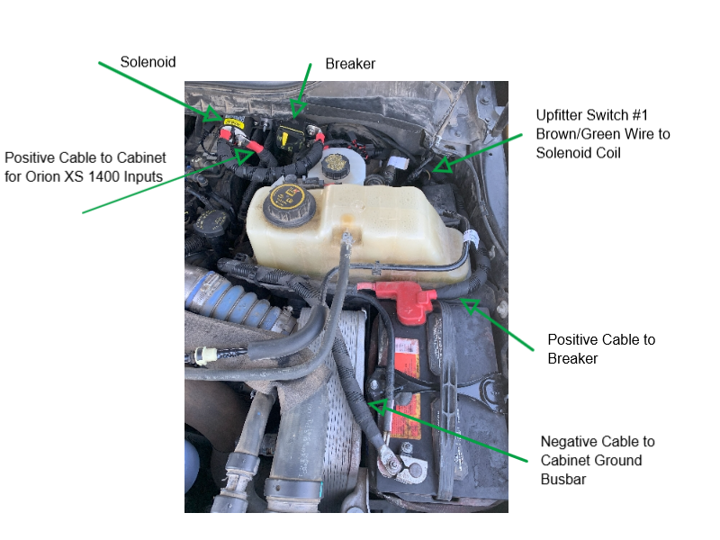
I decided to connect to the driver-side battery since that would minimize overall cable length. This battery’s negative lug had an unused M6 stud to which I connected the negative 2/0 cable. No such stud existed on the positive side, so I drilled out the flat part of the truck’s positive lug and added my own M6 bolt for the 2/0 connection. I considered purchasing after market terminal lugs that include extra cable connection points, but decided against it for fear of screwing up the factory harness.
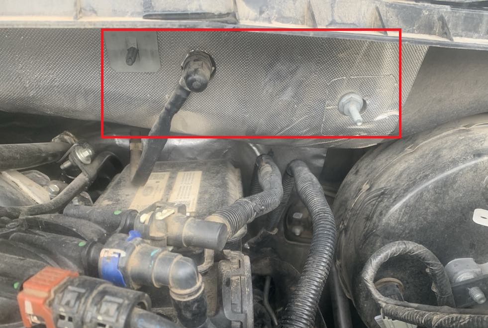
Another benefit to the driver side is the open space on the adjacent back wall that includes two unused M6 studs. Using the studs simplified the task of attaching a bracket (that I fabricated), to which I attached the breaker and solenoid.
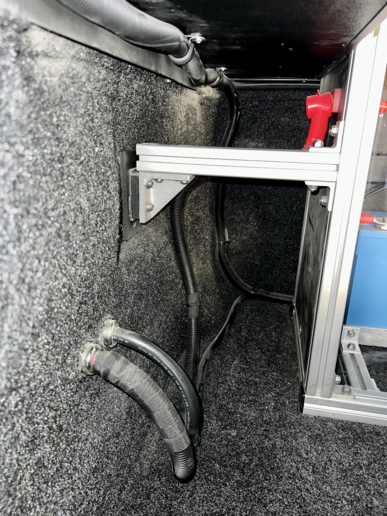
I ran all the 2/0 cable in 3/4″ split wire loom wrapped partially in tesa tape, including the negative cable for added protection from heat and other damage. I ran the negative cable from truck battery to electrical cabinet during the initial power system project, in anticipation of installing DC-DC chargers later on. Plus, that connection is necessary for grounding the entire system to the chassis at a single point.
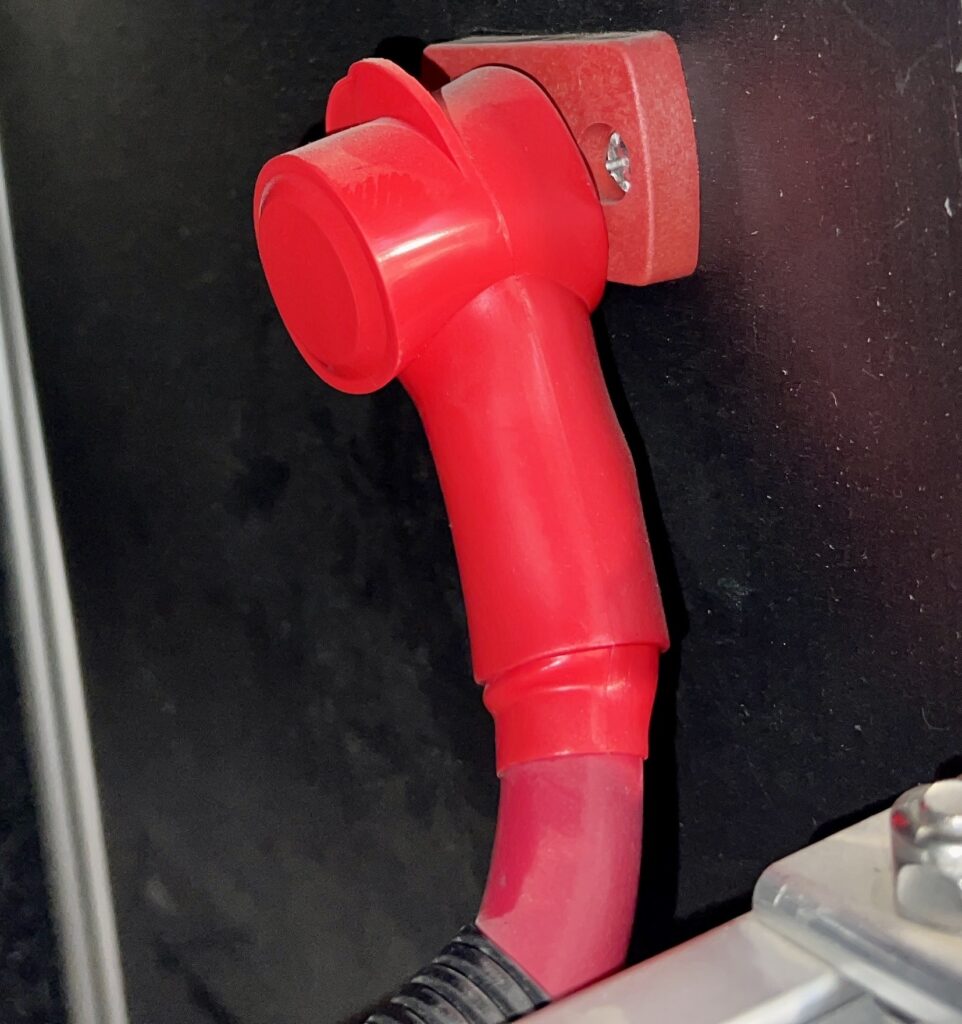
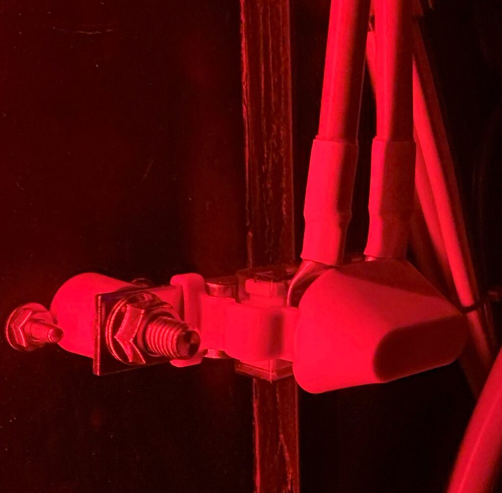
I passed both 2/0 cables through the truck bed wall via 3/4″ cable glands. The negative cable connects to the ground/negative bus bar around the back and inside the cabinet. The positive cable connects to a Blue Sea 3/8″ terminal feed-through connector and is sealed with a 1/2″ cable cap on the left side of the cabinet.
Solenoid Screw-up
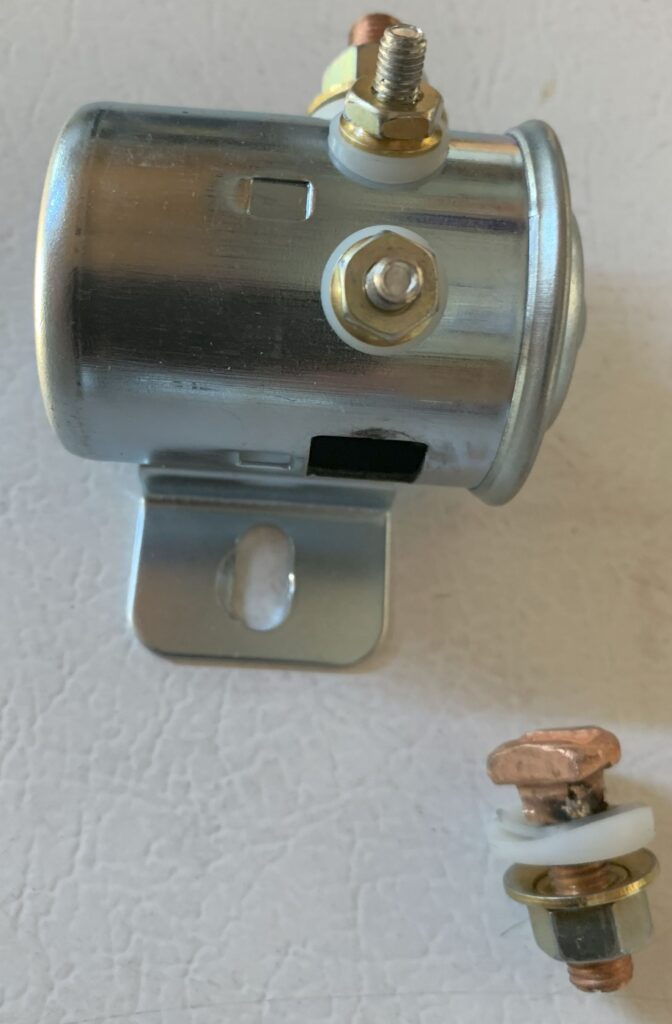
My big oh-shit moment on this part of the project had to do with the solenoid. I had initially purchased a 200A continuous duty Cole Hersee solenoid, which was supposed to be the better than the cheap Chinese knockoffs.
When I connected the 2/0 cable output and torqued it down, it began to break away from its internal solder joint. A burn mark also appeared after an initial power-on test.
I believe root cause was not using all the necessary nuts and washers, which for some reason were not included with my purchase. I should have received one set of hardware for torquing down the studs to the solenoid surface, and another set for torquing down the cable lugs. I could not find any documentation, but I figured out from pictures that hardware was missing. I planned to purchase the hardware later on, but proceeded without them to keep the project moving. This was foolish.
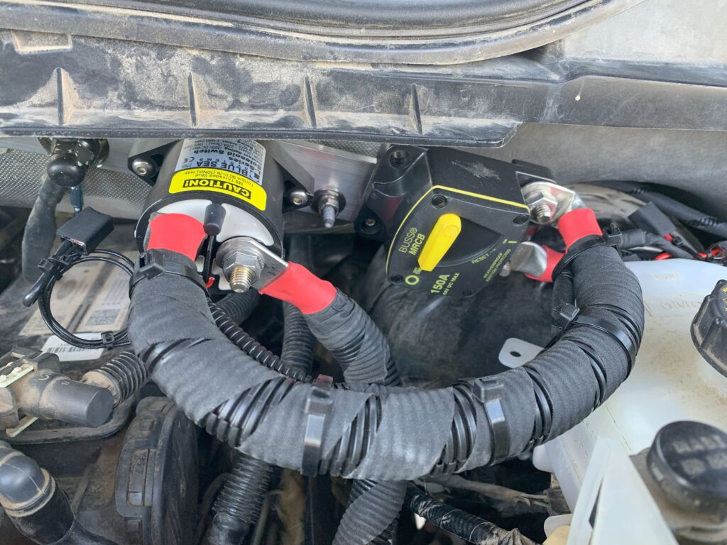
I ended up purchasing this Blue Sea 7765 150A L-series solenoid. This one is a rock-solid, hermetically sealed (zero water intrusion) unit that is mechanically superior to the Cole Hersee. Normally it is double the price, but I purchased mine “Used Like New” on Amazon for a little over $50.
I did not use heat shrink terminals for solenoid coil connections as planned. This was because I did not have stepdown connectors to go from 22 AWG on the coil to 14 AWG upfitter switch wire—and I did not want to wait for shipment. Also, I like to avoid soldering unless absolutely necessary. So, I used Wago connectors, wrapped them in tesa tape, and continued on with the project.
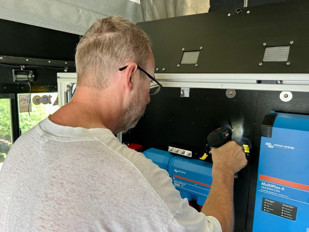
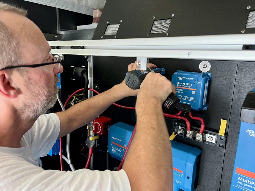
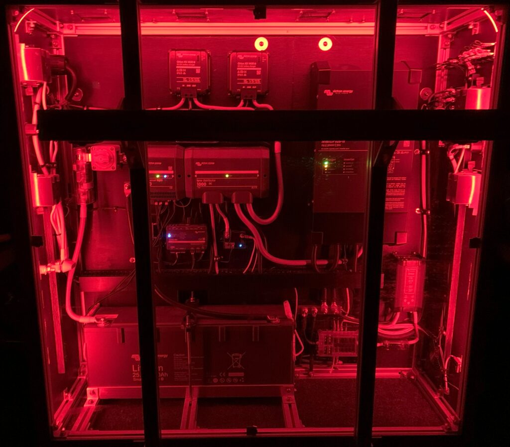
Inside the Electrical Cabinet
I made a cardboard template to get the layout I wanted in the top of the cabinet for the two Orion XS 1400 units, the Blue Sea 5196 3-circuit common fuse block, and the Blue Sea 2127 4-stud busbar. I was able to make cable connections between components with them loosely screwed into the cardboard. This is much easier to do laid out flat on a table than up inside the cabinet.
If I had not connected the cables to the units before screwing them into the cabinet—when I could still get a 360° view—I would have struggled to fit the 4 AWG cable into the Orion XS 1400 connectors. Even so I had to trim some strands to make them fit.
Clearly, using 4 AWG cable with ferrules would not be possible. However, 6 AWG cable should fit with or without them. To crimp ferrules for this purpose, Victron recommends a hexagonal rather than square shaped crimping tool.
Would I use 4 AWG cable again on a similar system? Probably. I love the advantages of bigger cable, but the challenge of making good connections chips away at those advantages.
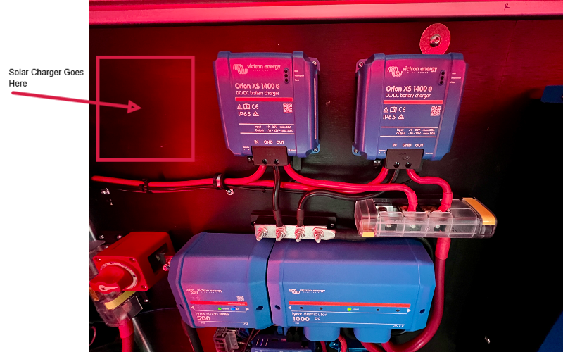
Once the chargers were mounted, I ran the input 4 AWG cables to the dual MRBF fuse terminals attached to the feed-through connector. These cables are protected by 75A MRBF terminal fuses.
I ran the positive fuse block and negative bus bar to position #4 on the Lynx Distributer using more 2/0 cable. The positive cable is protected by a 100A Mega fuse.
I debated downsizing these runs to 2 AWG, which would have been fine for this short distance (12-18 inches) where the output is twice the voltage and half the current. However, I stuck with 2/0 since the negative side is common (non-isolated) to both inputs and outputs on the Orion XS 1400s.
I placed components and sized fuse block and bus bar to allow for the future possibility of adding a solar charge controller. The image below shows where it would go. Also note the unused terminals on the left side of the bus bar and fuse block. Our Project M includes solar pre-wiring along with rails on the roof for attaching solar panels. All that remains is how to run solar cables into the cabinet. Perhaps two more feed-through connectors in the bottom left side of the cabinet.
The final step was to connect the chargers to the Cerbo GX with VE.Direct cables. As mentioned in an earlier post, connecting them to the cerbo makes DVCC an option, eliminating the need for additional protective circuitry. For example, DVCC prevents excessively low or high temperature charging that could damage the battery.
Configuration
The image below shows the main settings screen for one of the units. Each unit is configured the same.
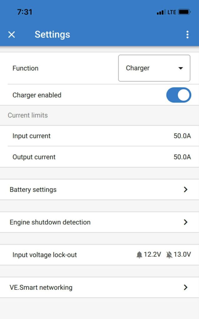
- In Battery settings, I set:
- Battery voltage = 24V
- Battery preset = Smart Lithium (LiFePo4)
- I enabled Engine shutdown detection and set Alternator type = Smart Alternator (12V), which provides redundant starter battery protection separate from our upfitter switch to solenoid coil connection.
- My choice of setting values for Input voltage lock-out are a bit more subjective. There is a Lock-out value and Restart value that by default are set to 12.5V and 12.8V respectively. I went with the following in an attempt to minimize possible chatter due to smart alternator voltage fluctuations:
- Lock-out value = 12.2V
- Restart value = 13.0V
- Other settings of interest, Charger enabled and Current limits, are set as desired while charging.
Final Thoughts
At the time of this writing, we have logged two months of travel with our two Orion XS 1400s and our generator has remained safely stowed back home in our garage. For the most part we achieved the charging independence we hoped for.
However, there have been comprises. Sometimes we camp farther away from the next days trailhead to have more drive/charge time. More often we simply use less power, skipping some convenience we might otherwise enjoy. On our last trip, we stayed for a night at a campground we wouldn’t normally choose because they had power hookups. This was because short drive times to trailheads, over the course of a month, was not allowing the house battery to charge long enough to balance and synchronize to 100% SOC.
We may add solar to the mix. Admittedly it’s better to have redundancy than not, because you never know when a charge source will be in short supply. It comes down to how inconvenient it is to go without, and what other project seems more important at the time. A blog post(s) covering a solar install may someday appear!
Parts List
Here is a list of items we purchased to build our system.
You can navigate the Excel spreadsheet below directly or download the file through the download button on the bottom right.
We are Amazon affiliates and appreciate your purchases through the provided links.
We are also Tnutz affiliates. They offer the lowest prices on the web for aluminum extrusions, brackets, and much else. Before ordering through Tnutz check out this page to learn how to save on shipping.
Thank you!