Series: All Victron RV Electrical
This series covers our build of an all Victron electrical system. Take what is helpful and leave the rest—build your system for your own needs. Cheers!
Note: We are not sponsored by Victron, but we are Amazon and Tnutz affiliates.
Part 4: Wiring and Configuration
Part 5: Orion XS 1400 – Concept
Part 6: Orion XS 1400 – Design
Part 7: Orion XS 1400 – Installation
Appendix A: Fuses and Breakers
Introduction
In the last post I covered design of the solar system. Here I cover installation and configuration, and end with closing thoughts on the series.
Installation
Installation began with mounting the panels on the roof, followed by wiring through the PV disconnect to the electrical cabinet, and ending with the charge controller.
Panel Mounting
We ordered our Four Wheel Camper Project M with the Yakima roof “tracks only” option. We thought it likely we would mount solar panels and/or other accessories. For simple campers like the Project M, options are a big part of the cost. The current price for this option (as of this writing) is $575. I feel it was worth the cost to ensure panels are mounted securely while the roof remains watertight.
Panel Brackets
There are four holes on the bottom of each panel frame along each side. These holes are the intended mount points. Since the width of the bottom of the panel frame is 1 3/8″, I planned to attach the panels to 1/8″ thick x 3″ wide aluminum flat bar brackets, which could then be fastened to the tracks at four points for each panel. The brackets would run the full length of the panels to add some extra rigidity.
The local aluminum supplier had 2 1/2″ wide flat bar in stock, which was wide enough for this purpose. Running the numbers, I calculated that four brackets (two per panel) times 1/8″ x 2 1/2″ x 64.6″ (panel length), would weigh 6.59 lbs in total. No big deal.
Nord-Lock Washers
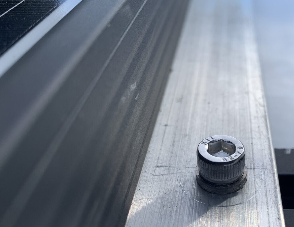
The biggest challenge was securely fastening the brackets to the Yakima tracks. Each track contains six Anchor Plate “A” M6 nuts which are 1/8″ thick. I determined that an M6 x 1.0 fastener bottoms out in the track after 5.5 turns. Since a 1/8″ thick nut is equal to 3.175mm, and the thread pitch is 1mm per turn, screw length matters. My first attempt with 16mm long screws bottomed out; 12mm was just right.
Keeping the screws fastened was a big concern. My father-in-law recommended Nord-Lock washers. He said they were the best lock washers you can buy and that he has had great success using them. From their product website:
The solution is composed of a pair of wedge-locking washers. Each washer has cams on one side and serrations on the other. When tightened, the serrations embed into the mating surfaces. As the cam angle (α) is greater than the thread pitch (β), a wedge effect is created, so movement only occurs across the cams – maintaining preload and preventing loosening.
I hesitated because of price. On the Fastenal website they are nearly $7 a pair in stainless steel. I needed 8 pairs—$56 for washers! I decided to go another route, but kept thinking about the poor outcome if the screws were to work themselves out. I took another look and purchased them on Amazon for just over $36 for 10 pairs.
After some research, I decided to tighten them to a somewhat low torque value of 35 in-lbs to avoid warping the tracks (which leads to loosening) and bottoming out with more turns. They loosened a bit and I re-torqued a couple of times over a settle-in period. Since then none have loosened.
Note: I also applied anti-seize, careful to keep it on the threads and off the mating surface where the Nord-Lock serrations embed.
Panel Grounding
I was not overly concerned with panel grounding—most DIY folks do nothing. But if it’s easy enough to take some steps, why not? The chance of an issue is not zero.
I attempted to follow the advice of FilterGuy from the DIY Solar Power forum:
If the mounting method is all metal and naturally connects the frames to the chassis, then make sure it is a good connection and call it good. Any additional grounding wires would almost certainly create ground loops. (Notice that with this, the frames are grounded to the chassis but there are no obvious grounding wires.)
I did the following for each panel:
- Sanded area around one panel frame hole to remove the anodized layer where it seats against the aluminum bracket.
- Applied thin layer of Noalox to that surface to prevent corrosion and enhance conductivity.
Everything on the roof is metal, but for charges to travel to the rest of the chassis when the top is up, the only path I am aware of is through the struts. This is not ideal. However, I felt the pros of not having extra wire running from the roof to the rest of the chassis outweighed the cons. Good enough for who it’s for.
Panel Wiring
On our travel trailer I made the decision to cut off the MC4 connectors on the solar panels and use butt splices to extend cables. I had read that these connectors were a weak point, due to poor quality and/or slight size differences between manufacturers. I had also read that crimping MC4 connectors onto cables properly can be a challenge.
For this project I changed my strategy. Because I purchased Renogy panels, I planned to buy Renogy cable extensions and adapters, readily available on Amazon. These should fit their own panel connectors well enough, plus I would not need to make my own MC4 crimp connections.
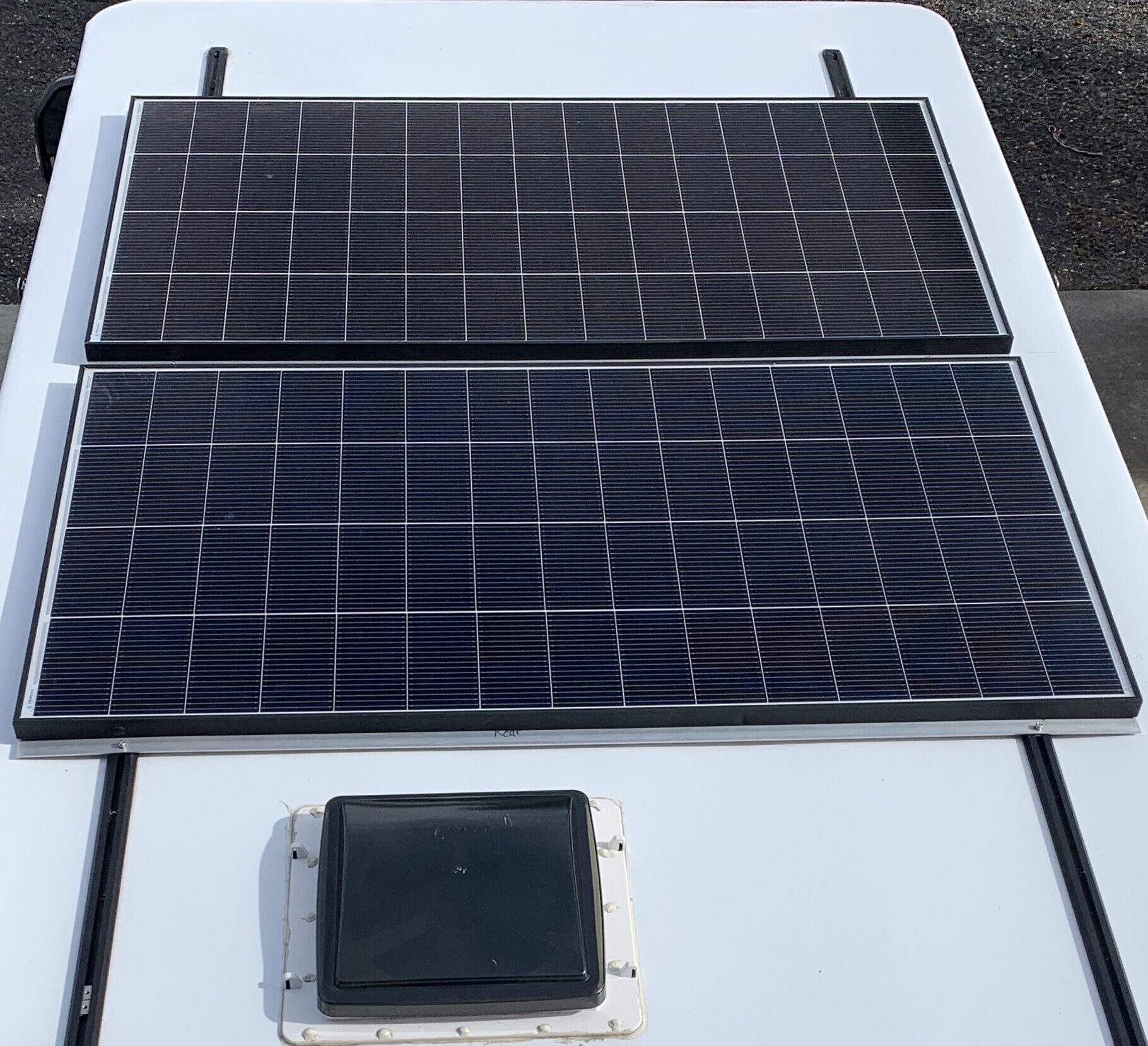
I was able to hide all cables and connections under the panels and brackets. A 90 degree SAE adapter at the roof port allowed that connection to fit just under the rear panel. To the 90 degree adapter I connected this Renogy SAE to MC4 adapter, one side going to the rear panel and the other running under the brackets to the front panel via this short 1.5 ft Renogy extension cable. The panels are close enough together that the series connection was completed by connecting the positive of one to the negative of the other; no extension necessary.
PV Isolator/Disconnect
Single-pole breakers are commonly used for the disconnect on RV solar arrays. However, double-pole breakers or switches that disconnect both positive and negative simultaneously are better. Since the negative side of a solar array does not share a common ground with the rest of the system, that side is floating and a potential difference—shock hazard—exists. For residential systems, double-pole disconnects are required.
On our travel trailer we went the single-pole route. For this system, particularly with higher array voltage, I planned to step up to a double-pole disconnect.
I considered either a breaker or a switch for the disconnect. As discussed in the last post, overload protection is unnecessary for a single series string, so the purpose of the breaker would be to act as a switch.
On Amazon, you can buy inexpensive Chinese-made double-pole breakers that come with an enclosure. However, these do not include test data for PV applications or UL listings. I believe it is a bad idea to purchase a component of unknown quality for interrupting high DC voltage.
I ended up purchasing an IMO True DC Isolator. I believe a switch purposefully designed for PV applications, rather than a breaker, is the better choice. It was an Occam’s razor sort of decision: if you want a switch, buy a switch. It should provide the fast switching and minimal arcing you want for high DC voltage.
Based on the specs, it should safely handle 900-1000 VDC for our double-pole implementation and operating current (~9A). I’m OK with a little over-engineering.
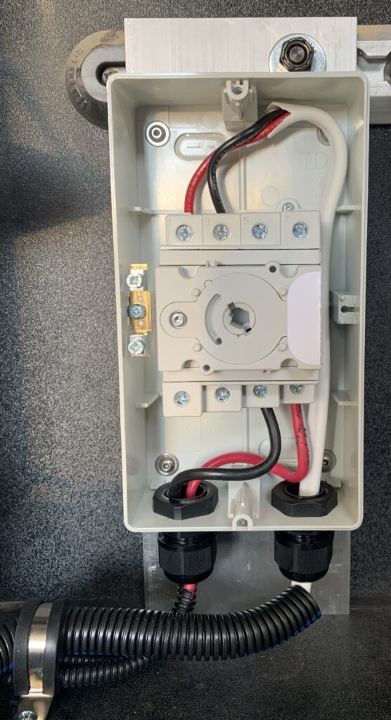
An important thing to keep in mind when switching the isolator/disconnect is that order matters. The proper way to power down the system, for example after a trip, is to disconnect the array before powering down the rest of the system, and vice versa to turn it back on. This is because voltage spikes on the PV side can damage the charge controller if not already energized on the battery side.
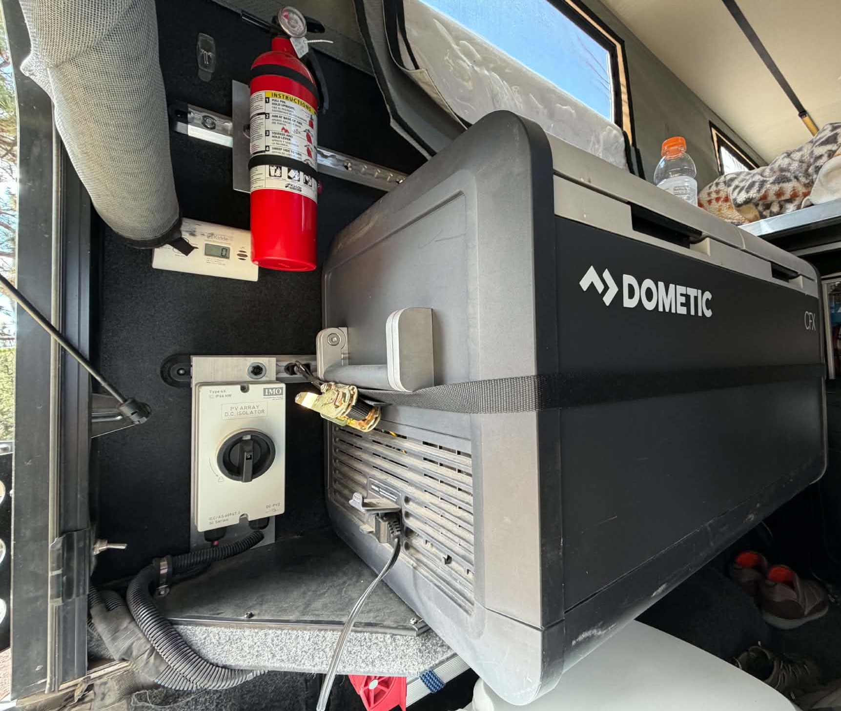
I placed it in the rear of the Project M so I can readily expedite a power-up or power-down. To power down, I open the rear hatch, turn off the solar array at the disconnect, and, via Bluetooth on my phone, turn off (open) the Lynx BMS contactor to power down the rest of the system.
PV Isolator to Electrical Cabinet
I used leftover 12/2 Ancor cable to run from isolator to cabinet, entering from the rear.
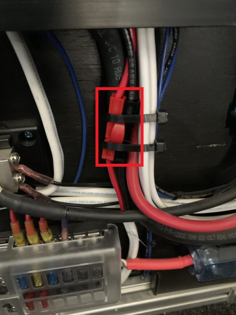
To facilitate future removal of the cabinet, I connected this run with Anderson Powerpole connectors. I purchased the connectors and crimp tool for an earlier project to supply 24V power to our diesel heater, with the expectation that they would be useful later on.
Anderson Powerpole connectors are common in the ham radio world, but are catching on for use in RVs. Their genderless design and secure mating are a big step up from loose-fitting cigarette-lighter connectors frequently used for DC applications.
Charge Controller
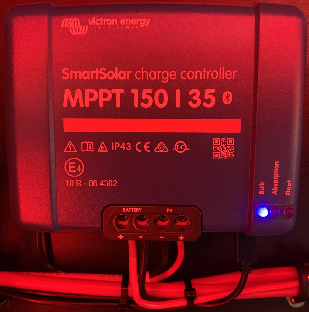
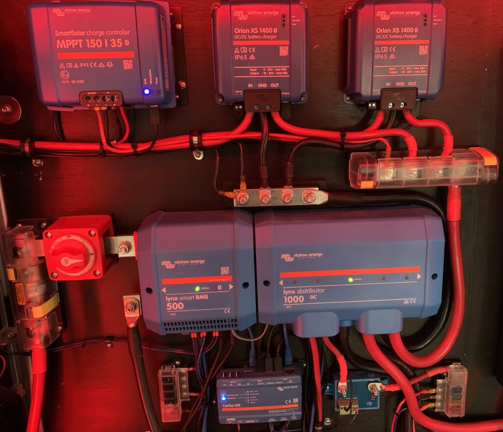
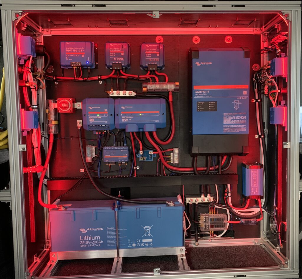
Once the charge controller was mounted, I attached an Anderson Powerpole connector to 12/2 cable and mated the Anderson to the PV run where it comes into the cabinet. I ran the cable across the cable raceway to the PV inputs of the charge controller.
I ran battery positive of the charge controller to the 3-circuit common fuse block, protected by a 40A MRBF terminal fuse, and battery negative and ground to the negative bus bar. As discussed in part 7, this fuse block and negative bus are also used by the two Orion XS 1400 DC-DC chargers, and connect to position #4 on the Lynx Distributor using 2/0 cable. The positive 2/0 cable is protected by a 100A Mega fuse on the Lynx.
The final step was to connect the charge controller to the Cerbo GX with VE.Direct cables. As mentioned in an earlier post, this makes DVCC an option, eliminating the need for additional protective circuitry. For example, DVCC prevents excessively low or high temperature charging that could damage the battery.
Configuration
Preconditions for initial configuration of the charge controller are as follows:
- PV disconnect in off position,
- Lynx BMS contactor turned off (open), and
- VE.Direct cable disconnected.
With the preconditions met, I followed the recommended connection order for electrical connections to perform initial configuration:
- Connect the battery: allow the solar charger to automatically recognise the system voltage (wait 10 seconds).
- It is recommended to verify system voltage: use VictronConnect or an external control display.
- Connect the PV.
- If applicable, connect the VE.Direct port.
The manual goes on to say:
The correct connection order is necessary to allow the automatic system voltage detection to setup properly. It is only allowed to connect PV first when the system voltage is manually set before connecting the battery. Not following the correct procedures can disable or damage the charger and/or the installation.
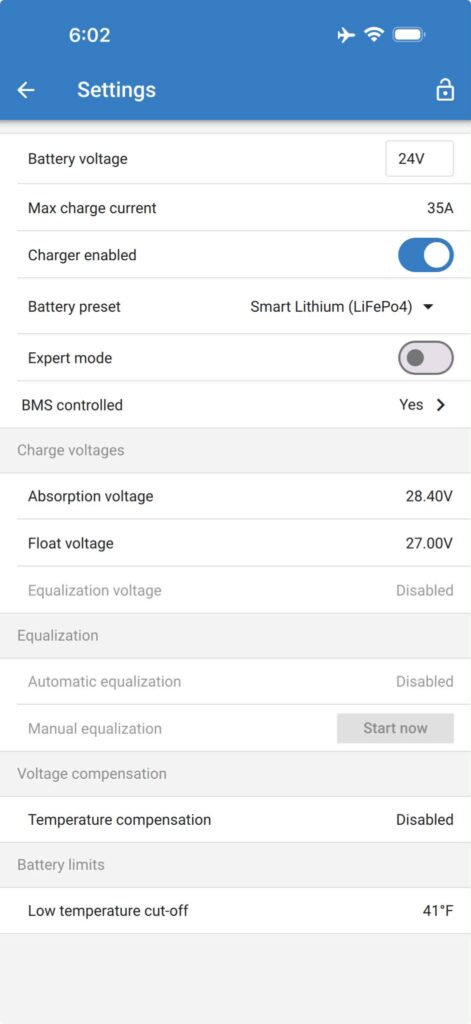
After performing the above steps, I kept the default Battery settings with one exception:
Battery preset = Smart Lithium (LiFePo4)
This applies to our system because our battery is a Victron Smart Lithium. I should note that DVCC overrides this setting when enabled, which is the case for our system.
Series Conclusion
If you are still not a Victron fanboy, that’s OK. There are alternatives that might better fit your needs and skill set. EcoFlow has some all-in-one kits that show great promise.
The intention of this series was to show what I did, to help someone going down a similar path, and to have a conversation with my future self to help recall some of the details.
The work to complete this system has been a long road that has consumed a mountain of calendar time. It would be disingenuous to say it’s because we are on the road half the time traveling and exploring—it would have taken a long time regardless. A long time researching, planning, designing, rethinking, reworking, purchasing, building, and writing this series. These are some of the milestones:
- January 2023: Ordered Four Wheel Camper Project M.
- May 2023: Picked up Project M from Mule Expedition Outfitters in Issaquah, WA.
- May 2023 – January 2024: Used Project M for occasional 1-2 night trips; was a glorified canopy on longer trips with our ORV travel trailer.
- May 2024: Longest trip to date with Project M (2.5 weeks). This was a spartan configuration: no power system or fridge. Ice chest magically mixes water from melted ice into every container.
- July 2024: Completed initial phase of power system. We had full power in the Project M and could now use our new Dometic Fridge/Freezer. At this point we relied on charging via generator or shore power only.
- December 2024: Posted parts 1 – 4 of this series covering initial phase of power system.
- February 2025: Installed 24V female socket for Starlink mini.
- March 2025: Added microwave/desk/storage shelf to front of electrical cabinet.
- May 2025: Sold the ORV travel trailer, which we had not used since January 2024.
- August 2025: The Orion XS 1400 was released, we received two units, and we completed the DC-DC charger installation. We were now ready to travel without the generator.
- October 2025: Installed 24V Anderson Powerpole outlet for upgraded diesel heater; moved all 24V loads (fridge, Starlink, diesel heater) to 4-circuit fuse block.
- November 2025: Posted parts 5 – 7 of this series covering the addition of the DC-DC charging system.
- February 2026: Completed solar install.
- August 2026: Completed water system install; separate blog series coming.
- October 2026: Posted parts 8 – 10 covering solar install; all Victron RV electrical series complete.
Parts List
Here is a list of items we purchased to build our system.
You can navigate the spreadsheet below directly or open it in a separate tab.
We are also Tnutz affiliates. They offer the lowest prices on the web for aluminum extrusions, brackets, and much else. Before ordering through Tnutz check out this page to learn how to save on shipping.
Thank you!
We are Amazon affiliates and appreciate your purchases through the provided links.
Open in Google Sheets