Series: All Victron RV Electrical
This series covers our build of an all Victron electrical system. Take what is helpful and leave the rest—build your system for your own needs. Cheers!
Note: We are not sponsored by Victron, but we are Amazon and Tnutz affiliates.
Part 4: Wiring and Configuration
Part 5: Orion XS 1400 – Concept
Part 6: Orion XS 1400 – Design
Part 7: Orion XS 1400 – Installation
Appendix A: Fuses and Breakers
Introduction
In the last post I discussed what led to our decision to add solar. Here I cover design of that system.
Same Charge Controller Twice as Nice on a 24V System
Before jumping into design, it’s worth reflecting on a key advantage of 24V and larger system voltages with regard to solar. In Part 1 there is a section where I discuss the reasons why I designed a 24V system. I end that section as follows:
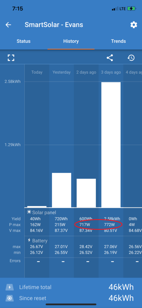
For example, the Victron MPPT 100|50 charge controller I installed on our travel trailer can be used to charge either a 12V or 24V system, however it has a hard current limit of 50A. This means it is limited to 700W charging on 12V systems and 1400W on 24V systems.
Moving from 12V to 24V systems doubles potential array size for a given controller.
Not surprisingly, there is a correlation between maximum charge current, wattage, and price. The table below compares retail prices (as of this writing) for 150V Victron SmartSolar units.
| Victron Model | Max Charge Current | Max PV Wattage (12V) | Max PV Wattage (24V) | Approx. Price |
|---|---|---|---|---|
| SmartSolar 150/35 | 35A | 500W | 1,000W | $184 |
| SmartSolar 150/45 | 45A | 650W | 1,300W | $218 |
| SmartSolar 150/60 | 60A | 860W | 1,720W | $310 |
| SmartSolar 150/70 | 70A | 1,000W | 2,000W | $402 |
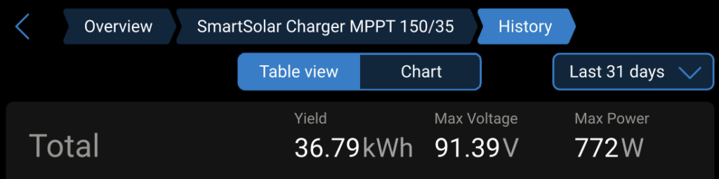
The 150V/35A unit is the one we purchased for our 640W array. On a 12V system we would have needed to step up to the 150V/45A unit, at greater cost and less wiggle room with regard to current and power (650W max).
Choosing Panels
All other design hinges on choice of solar panels. There is much that goes into panel selection worth reading about, but here I’ll focus on my primary concerns: weight, dimensions, power, and voltage.
As discussed in the Requirements section of the last post, the goal is to have as much solar as possible, right up to the space and weight constraints of the roof.
Weight is somewhat subjective. I looked for panels that were relatively light for the wattage. As discussed in the last post, we bought 60lb struts and a ratcheting cargo bar used as a jack to get a better handle on the weight issue.
To determine panel dimensions that are possible, you need to take measurements. The image of our Project M roof below shows what we had to work with.
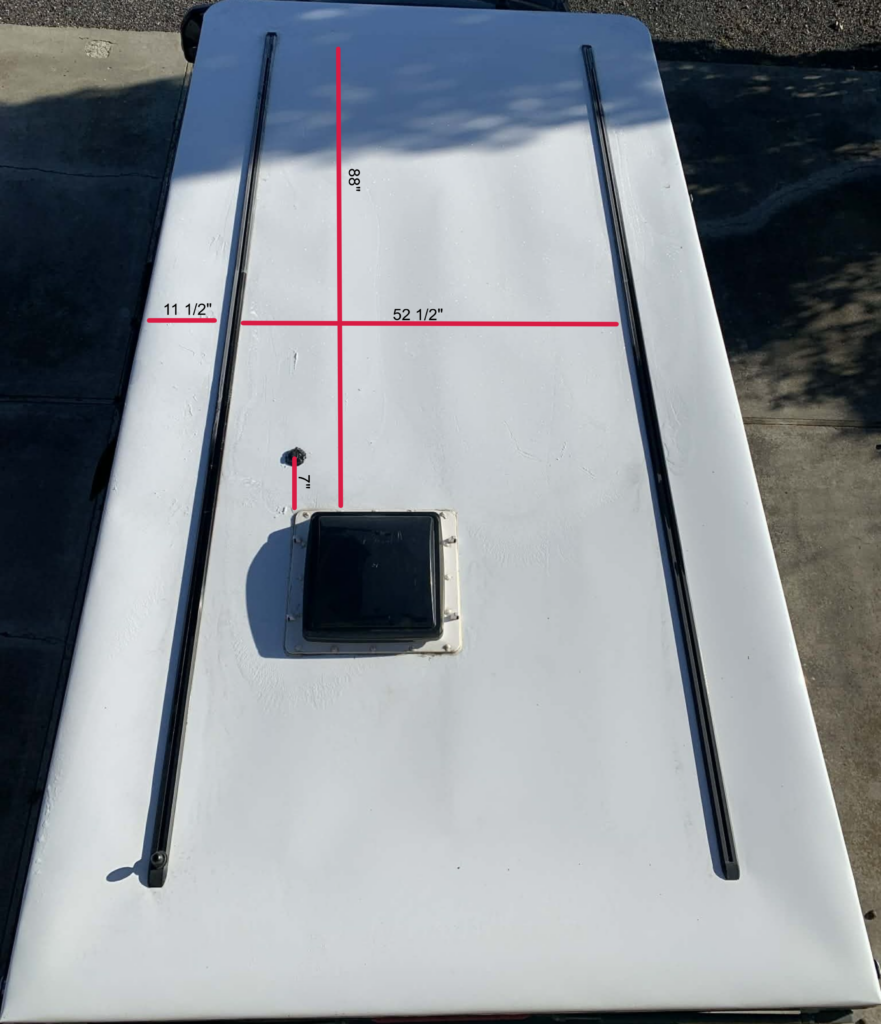
A strategy to keep weight to a minimum and allow for flexibility in panel size was to place them in a continuous block forward of the Maxxfan. I prefer fewer large panels rather than more small ones to minimize connections and wasted space. This left the unused Yakima tracks to the rear of the Maxxfan available for accessories such as our Starlink Mini mount.
I was initially interested in the Rich Solar brand, but buying anything larger than 250W required purchasing an eight-panel pack. Later I discovered this two-pack of Renogy 320W solar panels on Amazon. The weight per panel was more than that of the 250W Rich Solar panels, 32.9lbs vs 26.9lbs. And, the physical size (64.6″ x 34.7″) is a nice fit for our roof. I was also happy that this would mean a 640W array rather than 500W.
Another important consideration with regard to panels is voltage. As with power, I believe the bigger the better. This is even more important for system voltages greater than 12V, since charge controllers require greater PV side voltage to charge larger system voltages. Greater voltage also improves charging in low-light conditions.
Panel voltage is a function of the number of series-connected cells inside a panel. Common cell counts are 36, 60, and 72. Cell count correlates with the physical dimensions of a panel—the more cells, the larger the panel. For both our travel trailer and this project, 60 cells seems to be the sweet spot between panel voltage (~36 operating volts) and panel dimensions we can work with.
The more common way to boost PV voltage is to connect multiple panels in series. Later I discuss doing both to address our concern with small gauge solar pre-wiring.
Electrical Design
The diagram below shows the major components of the entire electrical system, with the exception of the Cerbo GX. See Part 2 of this series for a discussion of the main components and Part 6 for the parts associated with charging from the truck alternators. Here the focus is solar.

The two Renogy 320W solar panels in the upper right corner are wired in series with 12 AWG cable and combine for 640W total.
The solar panels connect to the Project M roof port through a single SAE connector and run through the pre-wired-for-solar cable, 10 AWG from the factory, to the IMO solar isolator/disconnect.
The output of the disconnect runs to the electrical cabinet, via 12 AWG cable, and into the photovoltaic (PV) ports on the MPPT 150 | 35 solar charge controller.
The battery output of the charge controller connects to a Blue Sea 5196 3-circuit common fuse block with 10 AWG cable, and is protected by a 40A MRBF terminal fuse. This fuse block also contains the output of the two Orion XS 1400 units that provide DC-DC charging.
The output of this common fuse block connects to the Lynx Distributor with 2/0 cable and is protected by a 100A mega fuse.
Why are there no fuses on the PV-side?
The most shocking thing (literally?) I learned this go-round was that a single series string does not require overload protection. Unlike most power sources, a solar panel specifies its short-circuit current. I had not thought about what this implies—if a conductor can handle the short-circuit current, there is no need to protect it.
For our solar panels the specified short-circuit current and optimal operating current are nearly equivalent, 8.92A and 8.46A respectively. And the specified maximum series fuse rating is 20A—fault current can never reach that.
Cable fuses are necessary if there are multiple series strings and the sum of the short-circuit currents exceeds the maximum fuse rating. This was the case for our travel trailer array, which consisted of three solar panels connected in a three-parallel (3P) configuration—effectively three series strings—which necessitated a fuse for each panel branch. For further reading on this topic I recommend this Explorist.life article.
Isn’t that cable too small?
I knew the array would need to have a large operating voltage and small current, since I planned to route the output through the single solar roof port and 10 AWG pre-wire from the factory. This was a key driver in the decision to purchase relatively high-voltage panels (60 cells) and connect them in series.
Historically, parallel panel configurations are preferred over series because of shading—a shaded panel can disable the rest of the panels in that series string. However, for panels with bypass diodes, which allow current to pass through them if shaded, I do not believe this is a serious issue. Also, on a small RV like ours, if one panel is shaded the other likely is as well.
The math shows the small cable in our design is sufficient—voltage drop and current handling are not a problem.
Round-trip wires sizes on the PV side are as follows:
- Roof wiring (panel leads + extensions): 11ft round trip (12 AWG)
- Roof port → PV disconnect: 12ft round trip (10 AWG)
- PV disconnect → Charge controller: 40ft round trip (12 AWG)
At peak sun, let’s say:
Current ≈ 9A
Operating voltage ≈ 72V
We’ll calculate the voltage drop of each section separately:
Resistance values (copper)
- 12 AWG ≈ 1.588Ω / 1000ft
- 10 AWG ≈ 0.999Ω / 1000ft
Voltage Drop by Section
A) Roof wiring — 11ft round trip (12 AWG)
B) Roof port → PV disconnect — 12ft round trip (10 AWG)
C) PV disconnect → Charge controller — 40ft round trip (12 AWG)
Total Voltage Drop
Percent Voltage Drop @72V:
Power Loss
The losses would be:
- ~7–8W at peak sun
- ~4–5W at 400W output
- ~1–2W in partial sun
Negligible.
Impact of High PV Voltage on Components
Careful selection of charge controller, fuses, and PV disconnect is critically important for systems with a high array voltage. Ensure these are rated for the DC voltages they will be subjected to. If rated voltage is exceeded, even momentarily, it can be catastrophic—high voltage can arc and damage components.
PV Voltage and Temperature
A subtle but important fact is that PV voltage increases as temperature decreases. The manual for the Victron charge controller warns:
Careful: when calculating the number of panels that can be used in series, make sure to take both its Open circuit voltage (Voc) and its Temperature coefficient into account. At ambient temperatures below 25°C, the Voc will be higher.
The specification for the temperature coefficient of Voc for each of our panels is −0.26%/°C. This means for every 1°C the cell temperature drops below 25°C, Voc rises by about 0.26%.
Let’s assume a cell temperature of −18°C (approximately 0°F). For one of our panels, where βVoc is the panel’s temperature coefficient for open-circuit voltage:
For our 2S panel configuration:
This shows that the safety margin for a 100V controller is very small, which is why I made the decision to step up to a 150V unit.
Next Up
In the next post I cover installation of the entire solar system. On the seventh day I rested.
Parts List
Here is a list of items we purchased to build our system.
You can navigate the spreadsheet below directly or open it in a separate tab.
We are also Tnutz affiliates. They offer the lowest prices on the web for aluminum extrusions, brackets, and much else. Before ordering through Tnutz check out this page to learn how to save on shipping.
Thank you!
We are Amazon affiliates and appreciate your purchases through the provided links.
Open in Google Sheets